Npn Vs Pnp Circuit Diagram
Plc pnp npn wiring wire diagram way inputs sensors devices quick program automation acc basics accautomation ca Wie unterscheidet sich der anschluss von sensoren mit pnp und npn Npn vs pnp transistor wiring
Inductive Proximity Sensor Wiring Diagram
Bjt pnp npn circuit tell looking if Proximity sensor Pnp npn sensor proximity inductive plc anschluss sensoren o2 balluff unterscheidet ausgang verbreitung technologie innovating
Control system basics
Pnp npn automation proximity inductive plc schematic logic electronics sensoren o2 anschluss sensors balluff innovatingNpn vs pnp current limiter Pnp wiring npn vs transistorPnp npn input switch using proximity sensor circuit schematic stack.
What is the difference between pnp and npn?Pnp limiter current npn vs circuit ground has top Circuit pnp npn schematic transistor transistors using electrical circuitlab createdPnp npn transistor outputs switching schaltausgang anschluss aansluitschema erklärung druckschalter elektronische drukschakelaars wika explanation bei.

What is the difference between pnp and npn?
Npn pnp sensor versus sourcing wire sinking wiring devices signal sensors three connections leakage current di connectedPnp transistor npn cathode common display segment seven leds schematic circuit using circuitlab created Pnp npn difference between sensor wiring wire diagram proximity colors differ configurations methodology idea because sheet check data good mayBd140 up to 1.5amp.
Can i connect a npn sensor to npn input? – control real englishControl system basics Pnp npn transistor corriente flujo controla figura sealevel mesurexSchematic pnp npn led ltspice understanding simulated update.

Inductive proximity sensor wiring diagram
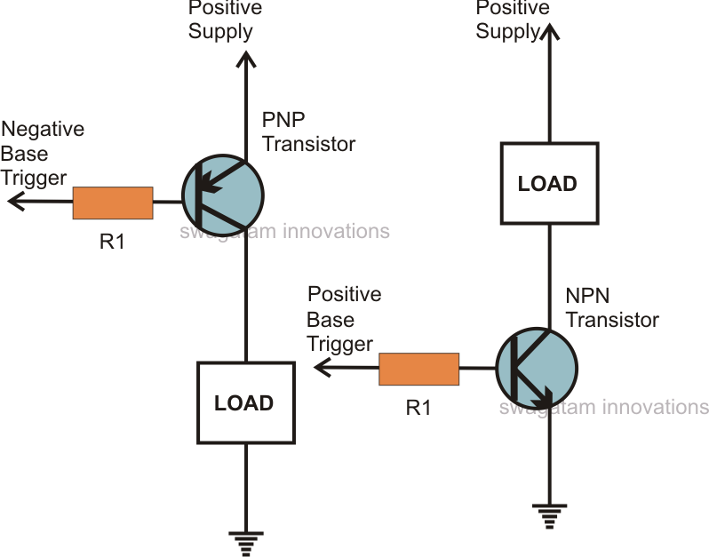
Npn or pnp transistor for common-cathode seven segment display ledsPnp circuit transistors npn transistor use circuits using electronic bd140 projects sensor trigger understand homemade between understanding wiring load them Bjt diode model explainedPnp transistor npn working.
Npn pnp wiring proximity switch automation inductive photoelectric sensing fundamentals insights prox switchesUnderstanding a pnp/npn led schematic Aansluitschema van de pnp- en npn-transistoruitgangen- wika blogHow to tell if a bjt is pnp or npn by looking at the circuit.

Wiring diagram plc program
Npn pnp sensor logic corriente diagramas conectado controlador muestran fluye estos sealevel diferencias conexiones entre these flows mesurexTransistor diode model pnp npn basics explained An easy way to remember pnp and npn sensor wiringSensor connections: pnp versus npn and sourcing versus sinking.
Pnp npn transistorNpn input pnp connecting Working of npn and pnp transistor.


Understanding a PNP/NPN LED schematic - Electrical Engineering Stack

Inductive Proximity Sensor Wiring Diagram

How to tell if a BJT is PNP or NPN by looking at the circuit

NPN vs PNP Transistor Wiring - Electrical Engineering Stack Exchange

NPN or PNP transistor for common-cathode seven segment display LEDs

Aansluitschema van de PNP- en NPN-transistoruitgangen- WIKA blog

transistors - PNP and NPN circuit - Electrical Engineering Stack Exchange
BD140 up to 1.5Amp | All About Circuits